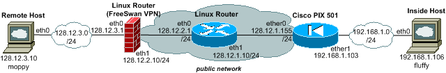
Network Layout
Introduction

Pictured left: Cisco Pix 501 security appliance for firewalling and VPN connectivity, incl. site-to-site VPN (<=10MB/s). 133MHz AMD SC520 Processor, 16 MB RAM, 8MB Flash [inside view]
![[inside view]](images/ciscopix501-inside.jpg)
Cisco's smallest security appliance PIX 501 is a solid device for building site-to-site IPSEC VPN tunnels with speeds of more then 3 MB/s. Although surpassed by Netscreens 5 series in terms of features and flexibility, it handles standard setups easily. Here we describe a site-to-site VPN tunnel setup with Linux. Although there are descriptions on the net, none covers NAT on the internal interface for only inbound connections to the 'inside' network. The network drawing above shows the setup used in the examples below.
The Linux router and Freeswan VPN host together with the internal and external system are set up in VMware, running 4 instances simultaenously. The Linux Router in the middle simulates the Internet, providing a ISP interface to each VPN side while allowing to view the network traffic to ensure packets are truly encrypted.
Setting up the Cisco PIX 501
Before we start working on the Cisco PIX 501, we wipe out all old setting to start from scratch. Before we configure complex settings, we set up and verify simple routing first.
mypix> ena
 Password:
 mypix# conf t
 mypix(config)# clear configure all
 pixfirewall(config)# wr mem
 Building configuration...
 Cryptochecksum: 311122df f423128e d2d308ea b99179b6
[OK]
If we cannot reset the PIX because the 'enable' password is lost, Cisco's password recovery procedure clears out the password by executing a tftp-loaded image at the boot monitor prompt of the PIX. The configuration stays untouched, only the passwords are wiped out. After creating a 'virgin' PIX with 'clear configure all', we set up the base IP configuration.
ip address inside 192.168.1.103 255.255.255.0
ip address outside 128.12.1.155 255.255.255.0
route outside 0.0.0.0 0.0.0.0 128.12.1.10
After configuring the Interfaces and setting the default route, we need to configure firewall rules to 'allow' traffic, here we use 'ping' for routing verification. The PIX instructions below create two access lists to permit icmp (ping) through the PIX in both directions.
access-list inside_access_in permit icmp any any
access-list outside_access_in permit icmp any any
Next, we need to bind the new access lists to the PIX internal and external interfaces.
access-group inside_access_in in interface inside
access-group outside_access_in in interface outside
Finally, we expose the internal network 192.168.1.0 to the outside interface of the PIX.
static (inside,outside) 192.168.1.0 192.168.1.0 netmask 255.255.255.0Of course, only in a lab setup! Pinging all IP in the network chain ensures routing is OK. This is our complete PIX configuration for the network configuration above.
Configuring a IPSec VPN on the PIX 501

Now we are ready to configure the PIX for the VPN tunnel. First the basic settings. 'sysopt connection permit-ipsec' permits 'IPSec' packets on port udp 500 regardless of access lists or conduits. Then, a access list must be created and connected to a crypto map. This access list defines which packets should fall into the encrypted tunnel. The crypto map itself describes the peer VPN, the encryption algorithms and on which interface the tunnel terminates.
sysopt connection permit-ipsec
access-list 100 permit ip 192.168.1.0 255.255.255.0 128.12.3.0 255.255.255.0
crypto ipsec transform-set myset esp-3des esp-md5-hmac
crypto map mymap 10 ipsec-isakmp
crypto map mymap 10 match address 100
crypto map mymap 10 set peer 128.12.2.10
crypto map mymap 10 set transform-set myset
crypto map mymap interface outside
The 'crypto ipsec transform-set' command above specifies one or two IPSec protocols (ESP, AH or both), which is used for negotiation with the VPN peer. Now we configure the 'isakmp' setting for the key exchange. We enable IKE on the outside interface, set the identity name to the external IP address and we define the pre-shared secret identical to the peer's VPN secret. The 'isakmp policy' defines the parameters and algorithms used for the IKE key exchange.
isakmp enable outside
isakmp identity address
isakmp key dobsekred address 128.12.2.10 netmask 255.255.255.255
isakmp policy 5 authentication pre-share
isakmp policy 5 encryption 3des
isakmp policy 5 hash md5
isakmp policy 5 group 2
isakmp policy 5 lifetime 28800
Finally, we need to specify our translation scheme for the traffic coming from the inside network. 'nat (inside) 0' means packets are routed into the tunnel without any address translation applied.
access-list 101 permit ip 192.168.1.0 255.255.255.0 128.12.3.0 255.255.255.0
 nat (inside) 0 access-list 101
Our new PIX VPN configuration and all commands are here for copy&paste.
Configuring the Linux FreeSwan
Now we define the Linux FreeSwan IPSec parameters for the VPN tunnel termination on the other side (IP 128.12.2.10).
vi /etc/ipsec.conf:
config setup
    interfaces="ipsec0=eth1"
    klippsdebug=none
    plutodebug=none
    plutoload=%search
    plutostart=%search
    uniqueids=yes
#VPN tunnel to Cisco PIX 501
    conn pix501
    af=inet
    type=tunnel
    auth=esp
    authby=secret
    left=128.12.2.10
    leftsubnet=128.12.3.0/24
    leftnexthop=128.12.2.1
    right=128.12.1.155
    rightsubnet=192.168.1.0/24
    rightnexthop=128.12.1.10
    esp=3des-md5-96
    ah=hmac-md5-96
    auto=start
To finish the Linux FreeSwan configuration, we need to add the shared secret to /etc/ipsec.secrets, mapping it to the peer IP of our PIX. Finally, we can start the VPN connection with '/etc/init.d/ipsec start' and watch the noisy VPN tunnel establishment.
echo "128.12.2.10 128.12.1.155 PSK "dobsekred" >> /etc/ipsec.secrets
/etc/init.d/ipsec start
Monitor the VPN tunnel creation on our PIX
pixfirewall(config)# debug crypto isakmp
crypto_isakmp_process_block:src:128.12.2.10, dest:128.12.1.155 spt:500 dpt:500
OAK_MM exchange
SAKMP (0): processing SA payload. message ID = 0
ISAKMP (0): Checking ISAKMP transform 0 against priority 5 policy
ISAKMP: life type in seconds
ISAKMP: life duration (basic) of 3600
ISAKMP: encryption 3DES-CBC
ISAKMP: hash SHA
ISAKMP: auth pre-share
ISAKMP: default group 5
ISAKMP (0): atts are not acceptable. Next payload is 3
ISAKMP (0): Checking ISAKMP transform 1 against priority 5 policy
ISAKMP: life duration (basic) of 3600
ISAKMP: encryption 3DES-CBC
ISAKMP: hash MD5
ISAKMP: auth pre-share
ISAKMP: default group 5
ISAKMP (0): atts are not acceptable. Next payload is 3
ISAKMP (0): Checking ISAKMP transform 2 against priority 5 policy
ISAKMP: life duration (basic) of 3600
ISAKMP: encryption 3DES-CBC
ISAKMP: hash SHA
ISAKMP: auth pre-share
ISAKMP: default group 2
ISAKMP (0): atts are not acceptable. Next payload is 3
ISAKMP (0): Checking ISAKMP transform 3 against priority 5 policy
ISAKMP: life duration (basic) of 3600
ISAKMP: encryption 3DES-CBC
ISAKMP: hash MD5
ISAKMP: auth pre-share
ISAKMP: default group 2
ISAKMP (0): atts are acceptable. Next payload is 0
ISAKMP (0): SA is doing pre-shared key authentication using id type ID_IPV4_ADDR
return status is IKMP_NO_ERROR
crypto_isakmp_process_block:src:128.12.2.10, dest:128.12.1.155 spt:500 dpt:500
OAK_MM exchange
ISAKMP (0): processing KE payload. message ID = 0
ISAKMP (0): processing NONCE payload. message ID = 0 return status is
 IKMP_NO_ERROR
crypto_isakmp_process_block:src:128.12.2.10, dest:128.12.1.155 spt:500 dpt:500
OAK_MM exchange
ISAKMP (0): processing ID payload. message ID = 0
ISAKMP (0): processing HASH payload. message ID = 0
ISAKMP (0): SA has been authenticated
ISAKMP (0): sending INITIAL_CONTACT notify
ISAKMP (0): sending NOTIFY message 24578 protocol 1
VPN Peer: ISAKMP: Added new peer: ip:128.12.2.10/500 Total VPN Peers:1
VPN Peer: ISAKMP: Peer ip:128.12.2.10/500 Ref cnt incremented to:1 Total VPN
 Peers:1
crypto_isakmp_process_block:src:128.12.2.10, dest:128.12.1.155 spt:500 dpt:500
OAK_QM exchange oakley_process_quick_mode: OAK_QM_IDLE
ISAKMP (0): processing SA payload. message ID = 762002848
ISAKMP : Checking IPSec proposal 0
ISAKMP: transform 0, ESP_3DES
ISAKMP: attributes in transform:
ISAKMP: group is 2
ISAKMP: encaps is 1
ISAKMP: SA life duration (basic) of 28800
ISAKMP: authenticator is HMAC-SHA
ISAKMP (0): atts not acceptable. Next payload is 3
ISAKMP: transform 1, ESP_3DES
ISAKMP: attributes in transform:
ISAKMP: group is 2
ISAKMP: encaps is 1
ISAKMP: SA life duration (basic) of 28800
ISAKMP: authenticator is HMAC-MD5
ISAKMP (0): atts are acceptable.
ISAKMP (0): processing NONCE payload. message ID = 762002848
ISAKMP (0): processing KE payload. message ID = 762002848
ISAKMP (0): processing ID payload. message ID = 762002848
ISAKMP (0): ID_IPV4_ADDR_SUBNET src 128.12.3.0 255.255.255.0 prot 0 port 0
ISAKMP (0): processing ID payload. message ID = 762002848
ISAKMP (0): ID_IPV4_ADDR_SUBNET dst 192.168.1.0 255.255.255.0 prot 0 port 0
return status is IKMP_NO_ERROR
crypto_isakmp_process_block:src:128.12.2.10, dest:128.12.1.155 spt:500 dpt:500
OAK_QM exchange
oakley_process_quick_mode: OAK_QM_AUTH_AWAIT
ISAKMP (0): Creating IPSec SAs inbound SA from 128.12.2.10 to 128.12.1.155
 (proxy 128.12.3. 0 to 192.168.1.0) has spi 3280104057 and conn_id 3 and flags
 25 lifetime of 28800 seconds
outbound SA from 128.12.1.155 to 128.12.2.10 (proxy 192.168.1.0 to 128.12.3.0)
 has spi 1311507039 and conn_id 4 and flags 25 lifetime of 28800 seconds
VPN Peer: IPSEC: Peer ip:128.12.2.10/500 Ref cnt incremented to:2 Total VPN
 Peers:1
VPN Peer: IPSEC: Peer ip:128.12.2.10/500 Ref cnt incremented to:3 Total VPN
 Peers:1
Adding inbound NAT to our VPN connection
Having a VPN connection alone is sometimes not enough. By using NAT we can overcome routing obstacles if similar networks are used on either side of the tunnel, or to enforce traffic can only flow in one direction, eliminating the need to route traffic back.
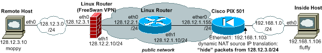
Let's configure dynamic NAT on our PIX for inbound VPN traffic coming from "Remote Host" as shown in the network layout above. We are going to hide the remote network 128.12.3.0 behind the PIX 501 internal interface, and only inbound connections from 'remote' are possible.
global (inside) 1 interface
access-list 102 permit ip 128.12.3.0 255.255.255.0 192.168.1.0 255.255.255.0
nat (outside) 1 access-list 102 outside
static (inside,outside) 192.168.1.0 192.168.1.0 netmask 255.255.255.0
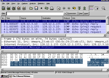
The screen capture on the inside host shows: It works. By simply removing all routing including default from host 192.168.1.106 we can prove it, also. With a working ping from 128.12.3.10, the packets MUST HAVE BEEN TRANSLATED.
Let's examine the statements:
- 'global (inside) 1 interface' adds the inside interface IP 192.168.1.103 to the global NAT pool.
- Access list 102 defines all IP traffic from 128.12.3.0/24 to 192.168.1.0/24.i
- The next 'nat' statement combines it all: Do dynamic NAT for packets coming from the (outside) translate into the IP of the inside (1) when the access list 102 matches, and, because the interface (outside) has a lower security level then inside (1), we need to add the identifier outside to complete the statement.i
- What else do we need to do? We need to expose the internal interface to the outside interface to make it reachable for packets, using a 'static' statement.
Adding outbound NAT to our VPN connection
Instead of inbound NAT, we now configure the opposite, outbound NAT on the PIX 501 for VPN traffic coming from 'inside' network 192.168.1.0/24 going to 'remote'. This will 'hide' our inside network from the remote side. Only outbound connections to the 'remote' network are possible.
global (outside) 1 interface
access-list 101 permit ip 192.168.1.0 255.255.255.0 128.12.3.0 255.255.255.0
nat (inside) 1 access-list 101
access-list 100 permit ip host 128.12.1.155 128.12.3.0 255.255.255.0
- We add the outside interface IP address to the global NAT pool 1.
- Then we create a access-list (101) describing the traffic we want to translate.i
- We build the NAT rule to translate traffic on the inside interface, coming from the 'inside' network and going to the 'remote' network, into the IP of the outside interface.
- Now we need to change our access list (100) which is describing the traffic that must be routed into the VPN tunnel. Because we changed the VPN traffic source IP, the old setting doesn't match anymore. Without updating it, our traffic would be routed to the public in clear!
vi /etc/ipsec.conf: rightsubnet=128.12.1.155/32here is a packet capture, the PIX setup commands and the Config for outbound NAT from 'inside'.
Links and Literature
- Cisco Systems: Cisco PIX Firewall Password Recovery Procedure Cisco Link, Local Copy Link
- Cisco Systems: Cisco PIX Firewall Hardware Installation Guide, Version 6.3, Local Copy Link
- Cisco Systems: Cisco PIX Firewall Command Reference, Version 6.3, Local Copy Link
- FreeS/WAN and a Cisco PIX 501 Link
- Enable SSH Link , PIX Log Messages, Local Copy Link